In this tutorial, you will composite a tree in the 2D landscape image.
1. First, you need a 2D landscape image.
2. Open a new scene in max.
3. Choose Rendering > Environment from the menu bar; the Environment and Effects dialog box is displayed, refer to Figure 1.
Figure 1
4. Choose the None button in the Background area of the Common Parameters rollout; the Material/Map Browser dialog box is displayed, refer to Figure 2. In this dialog box, choose Standard > Bitmap from the Maps rollout and choose the OK button; the Select Bitmap Image File dialog box is displayed. Browse to the location where the 2D landscape image is saved and select it. Next, choose the OK button; the 2D image will now act as a environment background for the scene.
Figure 2
5.Activate the Top viewport. Choose Create > Geometry in the Command Panel. Next, invoke the Plane tool from the Object Type rollout and create a plane in the viewport.
6. Activate the Perspective viewport and press Alt + B; the Viewport Configuration dialog box is displayed, refer to Figure 3. Make sure the Background tab is chosen and then select the Use Environment Background radio button. Next, choose the OK button to close the dialog box; 2D image is displayed as a background in the Perspective viewport.
Figure 3
7. Adjust the plane in the viewport to cover the landscape part of the scene, refer to
Figure 4.
Figure 4
Next, you will apply
Matte/Shadow material to the plane.
8. Choose Rendering > Material Editor > Compact Material Editor from the menu bar; Material
Editor dialog box is displayed. In this dialog box, select first sample slot. Next, choose the Standard button; the Material/Map Browser dialog box is displayed. In this dialog box, choose Standard > Matte/Shadow from the Materials rollout; the Matte/Shadow material is displayed in the selected sample slot.
Note: If the mental ray renderer is used, you need to use
Matte/Shadow/Reflection material for the plane.
9. Make sure the plane is selected in the viewport and then choose the Assign Material to Selection button from the Material Editor dialog box; the Matte/Shadow material is applied to the plane. Press Shift + Q to view the effect of Matte/Shadow material on the plane.
Now, you will add a tree to the scene.
10. Choose Create > Geometry in the Command Panel. Next, select AEC Extended from the drop-down list located below it.
11. Invoke the Foliage tool from the Object Type rollout; various rollouts for the Foliage tool are displayed in the Command Panel. Choose Euphorbia, Large Succulent from the Favorite Plants rollout. Next, click in the Top viewport to create a tree.
12. Set the height and location of the tree as per the 2D image used.
13. Choose Create > Lights in the Command Panel. Select Standard from the drop-down list located below it. Next, invoke the Omni tool from the Object Type rollout and click in the Top viewport to create a light.
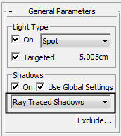
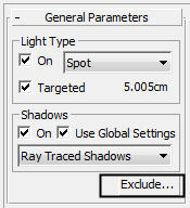
14. Make sure the Shadows check box is selected in the General Parameters rollout for the omni light.
15. Set the position of the omni light such that the direction of the shadow of the tree matches with the direction of shadows in the 2D image. The final rendered image is displayed, as shown in Figure 5.
Figure 5
.
Click the Like button below to stay updated !