Wednesday, December 11, 2013

mt003- How to create a ceiling fan

In this tutorial, you will learn to create a ceiling fan using various polygon modeling techniques.


3ds Max 2014 Textbook: http://www.cadcim.com/ProductDetails.aspx?ISBN=978-1-936646-54-8
Download eBook @ our eStore: http://ebooks.cadcim.com/product/autodesk-3ds-max-2014-comprehensive-guide
Kindle Edition: http://www.amazon.com/Autodesk-3ds-Max-2014-Comprehensive-ebook/dp/B00EUT714K

For more information visit: www.cadcim.com
Follow us @cadcimtech
Like our page: www.facebook.com/cadcim
eMail us at sales@cadcim.com

Click the Like button below to stay updated !

Sunday, December 1, 2013

mt002 - Create flower vase using Splines

In this tutorial, you will create a flower vase using different splines modeling techniques.

Click the Like button below to stay updated !

Thursday, August 8, 2013

mt001 - Creating blowing leaves simulation using Particle Flow in 3ds Max

In this tutorial, we will create a simple blowing leaves animation using the Particle Flow system in 3ds Max. This technique is also referred as “instancing” in other 3D application such as Maya.You need to follow the steps given next to complete this tutorial.

Step - 1
Download mt0001.rar from the following link and then extract contents of the rar file onto the disk: https://www.dropbox.com/s/6wfxrt54d9iv9nb/mt0001.rar

Step - 2
Choose the Project Folder button from the Quick Access Toolbar. The Browse for Folder dialog box is displayed. In this dialog box, navigate to the mt0001_leaves folder and then choose the OK button to close the dialog box.

Step - 3
Choose the Open File button from the Quick Access Toolbar. The Open File dialog box is displayed. In this dialog box, select leaves_start and then choose the Open button to open the file. This file contains a leaf geometry and a plane that will emit leaves in the scene. Also, it contains a camera.

Step - 4
Choose Create > Particle > Particle Flow Source from the menu bar and then create a Particle Flow system in the Top viewport. Next, press 6 to open the Particle View window, refer to Figure mt1-1. First event (PF Source 001) in the Event Display is the Global Event. By default, the Render operator is always present in the global event. The operators that are present in the global event, influence all particles in the scene. The other event (Event 001) is the local event. The two events are linked with each other via connection called wiring.
Figure mt1-1
Step - 5
Select the Birth 001 operator in the Event 0001 event. The Birth 001 operator is displayed in the Parameters panel. Set the Emit Stop spinner to 200.

Step - 6
In the Depot, click-drag the Position Object operator and place it over the Position Icon 001 operator in the Event 001 event; a red line is displayed. Next, release the mouse button to replace the Position Icon operator with the Position Object operator, refer to Figure mt1-2.
Figure mt1-2
Step - 7
Select the Position Object operator in Event 001, its properties are displayed in the properties panel. In the properties panel, choose the Add button and then click on the LeafEmitter geometry in the scene. As a result, the leaves will be emitted from the LeafEmitter, refer Figure mt1-3. Scrub the time slider, you will notice that now particles are being emitted from the LeafEmitter geometry.
Figure mt1-3
Step - 8
In the Depot, click-drag the Shape Instance operator and place it over the Shape operator in the Event 001 event; a red line is displayed. Next, release the mouse button to replace the Shape operator with the Shape Instance operator, refer to Figure mt1-4.
Figure mt1-4
Next, you will replace particles with the leaf geometry.

Step - 9
Select the Shape Instance operator in Event 001, its properties are displayed in the properties panel. In the properties panel, choose the None button and then click on the leaf geometry in the scene; the particles will now take shape of the leaf geometry.

Step - 10
Select the Display operator in Event 001, its properties are displayed in the properties panel. In the properties panel, select Geometry from the Type drop-down.

Step - 11
Scrub the time slider. Notice that now particles have taken shape of the leaf object, refer to Figure mt1-5.
Figure mt1-5
Step - 12
In the Shape Instance operator properties panel, set Scale and Variation spinners to 32 and 20, respectively.

Step - 13
Scrub the time slider to and notice the change in the behavior of the particles.

Step - 14
In the Speed operator properties panel, set SpeedVariationDivergence spinners to 3437, and 50, respectively.

Step - 15
Click-drag the Spin operator from the Depot and then place it after Rotation operator in Event 001.

Step - 16
In the Spin operator properties panel, set the Spin Rate and Variation spinners to 95 and 68, respectively.

Next, you will add a Wind space warp to simulate wind in the scene.

Step - 17
Choose Create > SpaceWarps > Forces > Wind from the menu bar and then create a wind icon in the Top viewport.

Step - 18
Rotate the wind icon as shown in Figure mt1-6.
Figure mt1-6

Step - 19
In the Particle View window, click-drag the Force operator from the Depot and then place it in Event 001.

Step - 20
In the Force operator properties panel, choose the Add button and then click on the wind icon in the Perspective viewport.

Step - 21
Select the wind icon in the scene and then choose the Modify tab. In the Parameters rollout, set the values of the following parameters:

Strength: 0.003

Select Spherical radio box.

Turbulence: 0.1

Icon Size: 23

Step - 22
Scrub the timeline to view the animation.

Step - 23
Now, open the Material Editor and create two sided material. Use leaf_color.jpeg and leaf_matte.jpeg images for diffuse and opacity maps, respectively.

Step - 24
In the Particle View window, click-drag the Material Static operator from the Depot and then place it after Shape Instance operator in Event 001.

Step - 25
Drag the leaf material from the Material Editor and drop it over the None button in the Material Static operator properties panel.

Step - 26
Adjust the camera angle as per your requirement.

Step - 27
Set a light blue color for the background from the Environments and Effects dialog box. You can also specify a background image.

Step - 28
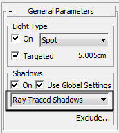
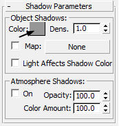
Now, add a directional light and turn on shadows.

Next, you will apply motion blur to the falling leaves.

Step - 29
Right-click on the PF Source icon. The Object Properties dialog box will be displayed. In the Motion Blur area of this dialog box, select the Enabled check box and then select the Image radio button.

Step - 30
Batch render the scene for final output.

Click the Like button below to stay updated !

Wednesday, June 5, 2013

3ds Max Design 2014 Book

Autodesk 3ds Max Design 2014 book introduces the readers to the basic features of 3ds Max Design 2014 through tutorials. The 3ds Max Design 2014 book caters to the needs of both the novice and the advanced users of the software. Written with the tutorial point-of-view and the learn-by-doing theme, the book is ideally suited for learning at your convenience and pace. This textbook will help you unleash your creativity and help you create simple and complete 3D models and animations. The textbook will help the learners transform their imagination into reality with ease.

Salient Features

  • Consists of 17 chapters that are organized in a pedagogical sequence covering modeling, texturing, modifiers, lighting, cameras, and animation and so on
  • Consists of 5 projects based on real-world models that will allow the users to apply the skills learned in the text
  • The first page of every chapter summarizes the topics that will be covered in it
  • Real-world 3D models and examples focusing on industry experience
  • Step-by-step instructions are added to guide the users through the learning process
  • Provides additional and important information in the form of notes
  • Self-Evaluation test, Review Questions, and Exercises are given at the end of each chapter so that the users can assess their knowledge

Table of Content
Chapter 1 - Introduction to Autodesk 3ds Max Design 2014
Chapter 2 - Primitive Objects-I
Chapter 3 - Primitive Objects-II
Chapter 4 - Splines-I
Chapter 5 - Splines-II
Chapter 6 - Lofting, Twisting, and Deforming Objects
Chapter 7 - Material Editor: Creating Materials
Chapter 8 - Material Editor: Texture Maps-I
Chapter 9 - Material Editor: Texture Maps-II
Chapter 10 - Material Editor: Controlling Texture Maps
Chapter 11 - Material Editor: Miscellaneous Materials
Chapter 12 - Interior Lighting-I
Chapter 13 - Interior Lighting-II
Chapter 14 - Animation Basics
Chapter 15 - Complex Animation
Chapter 16 - Rendering
Chapter 17 - Creating Walkthrough
Project 1 - Creating a Windmill
Project 2 - Creating a Diner
Project 3 - Architectural Project
Project 4 - Corporate Design Project
Project 5 - Creating a Computer Center
Student Project

Click the Like button below to stay updated !

Monday, April 29, 2013

How to use Vector map in 3ds Max 2014


The new Vector Map introduced in 3ds Max 2014 gives you ability to use vector maps as texture maps and then render them with dynamic resolutions (independent of the display resolution). The rendered graphics will remain crisp and clear at any resolution. This vector map supports AutoCAD PAT Hatch, AI (Adobe Illustrator), SVG, PDF, and SVGZ formats. You can also animate the textures using a PDF file that contains animated page transitions. In this tutorial, you will use the ai format with the format with the Vector Map.

Click the Like button below to stay updated !

Friday, March 15, 2013

maxtip0001-Tips and tricks in 3ds Max - I

1. To convert any object into editable poly follow second method instead of first method:

First Method:  If you right-click on the object in the modifier stack and choose Convert to Editable Poly from the shortcut menu displayed, the object in the modifier stack is replaced by Edit Poly and you cannot go back to the object level to modify the basic parameters of the object at a later stage of modeling , see Figure 1.

 Figure 1
                                                                          
Second Method: If you select the Edit Poly option from the Modifier List in the Modify tab; the Edit Poly modifier is applied above the object in the modifier stack. By doing so, you can go back to the object level and modify basic parameters of the object at any stage of modeling, see Figure 2.
        
Figure 2
     
2. Use Raytraced Shadows option from the General Parameters rollout for good quality shadows. Also, use grey shade in color swatch of Shadow Parameters rollout for realistic shadows, see Figures 3 & 4.

Figure 3
                                                                                 
  Figure 4 
                                                                                                                               
3.  To avoid reflection of light used in the scene on the objects such as glass, mirror, use Exclude option in the General Parameters rollout  to exclude these objects from the light, see Figure 5.
  Figure 5
                          
            4.  Use hdr  panoramic image as a background environment image to achieve 3D effect.


Click the Like button below to stay updated !

Thursday, March 14, 2013

Compositing a 3D object using Matte/Shadow material

In this tutorial, you will composite a tree in the 2D landscape image.

1. First, you need a 2D landscape image.

2. Open a new scene in max.

3. Choose Rendering > Environment from the menu bar; the Environment and Effects dialog box is displayed, refer to Figure 1.


Figure 1

4. Choose the None button in the Background area of the Common Parameters rollout; the Material/Map Browser dialog box is displayed, refer to Figure 2. In this dialog box, choose Standard > Bitmap from the Maps rollout and choose the OK button; the Select Bitmap Image File dialog box is displayed. Browse to the location where the 2D landscape image is saved and select it. Next, choose the OK button; the 2D image will now act as a environment background for the scene.


Figure 2

5.Activate the Top viewport. Choose Create > Geometry in the Command Panel. Next, invoke the Plane tool from the Object Type rollout and create a plane in the viewport.

6. Activate the Perspective viewport and press Alt + B; the Viewport Configuration dialog box is displayed, refer to Figure 3. Make sure the Background tab is chosen and then select the Use Environment Background radio button. Next, choose the OK button to close the dialog box; 2D image is displayed as a background in the Perspective viewport.


Figure 3

7. Adjust the plane in the viewport to cover the landscape part of the scene, refer to Figure 4.


Figure 4

Next, you will apply Matte/Shadow material to the plane.

8. Choose Rendering > Material Editor > Compact Material Editor from the menu bar; Material 
Editor dialog box is displayed. In this dialog box, select first sample slot. Next, choose the Standard button; the Material/Map Browser dialog box is displayed. In this dialog box, choose Standard > Matte/Shadow from the Materials rollout; the Matte/Shadow material is displayed in the selected sample slot.

Note: If the mental ray renderer is used, you need to use Matte/Shadow/Reflection material for the plane.

9. Make sure the plane is selected in the viewport and then choose the Assign Material to Selection button from the Material Editor dialog box; the Matte/Shadow material is applied to the plane. Press Shift + Q to view the effect of Matte/Shadow material on the plane.

Now, you will add a tree to the scene.

10. Choose Create > Geometry in the Command Panel. Next, select AEC Extended from the drop-down list located below it.

11. Invoke the Foliage tool from the Object Type rollout; various rollouts for the Foliage tool are displayed in the Command Panel. Choose Euphorbia, Large Succulent from the Favorite Plants rollout. Next, click in the Top viewport to create a tree.

12. Set the height and location of the tree as per the 2D image used.

13. Choose Create > Lights in the Command Panel. Select Standard from the drop-down list located below it. Next, invoke the Omni tool from the Object Type rollout and click in the Top viewport to create a light.

14. Make sure the Shadows check box is selected in the General Parameters rollout for the omni light.

15. Set the position of the omni light such that the direction of the shadow of the tree matches with the direction of shadows in the 2D image. The final rendered image is displayed, as shown in Figure 5.


Figure 5
.


Click the Like button below to stay updated !